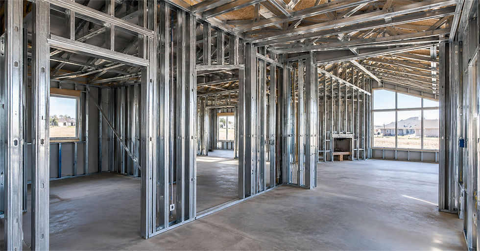
Interior Steel Framing Layout Guide

Planning an interior steel framing layout is an essential step in building straight, stable, and properly aligned partition walls. Before installing drywall studs and tracks for your interior steel framing layout, contractors need to establish wall locations, determine stud spacing, account for door openings, and coordinate framing with electrical, plumbing, and other building systems.
A well-planned interior steel framing layout helps reduce installation errors, material waste, and unnecessary adjustments during construction. Whether the project involves office partitions, apartment interiors, commercial spaces, or institutional buildings, the layout should follow the project drawings, manufacturer instructions, and applicable building requirements.
1. Review the Construction Drawings
Before marking the floor or installing tracks, review the architectural and framing drawings to understand the wall configuration and project requirements.
Identify the following details:
Wall locations: Determine where each partition begins and ends, including intersections and changes in direction.
Wall dimensions: Confirm the specified wall lengths, heights, and thicknesses.
Door and opening locations: Identify rough openings, door widths, and any framing requirements around openings.
Wall types: Distinguish between standard non-load-bearing partitions and walls requiring structural framing.
Building systems: Review the planned locations of electrical boxes, plumbing lines, HVAC components, and other services.
Performance requirements: Check any specified fire-resistance, acoustic, deflection, or other assembly requirements.
These details establish the basis for the layout and help prevent conflicts once installation begins.
2. Mark the Wall Layout
Accurate marking establishes the position of the partition before the framing components are installed.
Start by locating the wall lines according to the construction drawings. Use appropriate measuring tools and a chalk line or other suitable marking method to transfer the wall positions onto the floor.
Next, verify that the layout aligns with adjacent walls, door openings, columns, and other fixed building elements.
For walls that extend from floor to ceiling, the floor layout must also be transferred to the ceiling so that the upper and lower tracks align correctly. A laser level or plumb laser can help maintain alignment between the two surfaces.
Before proceeding, check:
Wall lengths and dimensions against the drawings.
The location of corners and wall intersections.
Door openings and other framed openings.
Alignment with existing walls and building elements.
Potential conflicts with building services.
Practical tip: Confirm the layout before fastening the tracks. Correcting an inaccurate wall line after installation has started can require additional labor and material.
3. Determine the Correct Stud Spacing
Stud spacing is one of the most important decisions in an interior steel framing layout. It affects how the wall is framed, how gypsum panels are supported, and whether the assembly meets its specified performance requirements.
Common layout dimensions for non-load-bearing interior partitions may include 16 inches or 24 inches on center. However, neither dimension should be treated as universally correct. The required spacing depends on the framing system, wall height, stud profile and thickness, gypsum board specifications, finish requirements, and applicable assembly details.
When determining stud spacing, consider:
The specified spacing in the project documents.
The height and configuration of the partition.
The thickness and capacity of the selected steel studs.
Gypsum board orientation and panel dimensions.
Requirements for tile, cabinets, fixtures, or other wall-mounted items.
Fire-resistance and acoustic assembly requirements.
Once the spacing is confirmed, mark stud positions consistently along the track layout. Keep the layout coordinated with board edges and joints wherever the specified system requires it.
For more information about spacing considerations, see our related guide on metal stud spacing for drywall.
4. Plan Track Placement
Tracks provide the horizontal framing members that receive the vertical studs at the floor and ceiling.
Select track profiles that are compatible with the specified studs and framing system. Track dimensions, material thickness, fastening methods, and installation details should follow the manufacturer's instructions and project specifications.
During layout and installation:
Position the floor track along the marked wall line.
Verify its alignment before fastening.
Mark or confirm stud positions along the track.
Position the ceiling track in line with the floor track.
Check that the tracks are secured using the specified fastening method and substrate requirements.
Where the design requires deflection or movement accommodation, use the specified deflection track or other approved detail rather than substituting a standard track without verification.
For non-load-bearing interior framing, ASTM C645 covers nonstructural steel framing members, while ASTM C754 addresses the installation of steel framing and furring to receive screw-attached gypsum panels. Always confirm the applicable editions and project requirements.
5. Account for Door Openings and Wall Intersections
Door openings, corners, and intersecting partitions require careful planning because they can change the normal stud layout.
Door openings
Locate each opening according to the construction drawings. Confirm the required opening dimensions and provide the specified jamb studs, headers, and additional reinforcement where required by the framing design.
Do not assume that every door opening uses the same framing configuration. Requirements can vary with door size, wall height, stud system, hardware, and whether the wall is nonstructural or structural.
Wall intersections
At T-junctions and corners, plan how the adjoining walls will connect and how the gypsum board edges will be supported. The selected detail should provide the required fastening surfaces without creating unnecessary interference between framing members.
Wall ends
Check how each partition terminates at columns, existing walls, glazing systems, or other building elements. The connection and perimeter details should follow the specified assembly.
Planning these locations before installing the main run of studs helps avoid improvised framing solutions later.
6. Coordinate the Layout with Building Services
Electrical, plumbing, and mechanical systems can affect where studs and openings need to be located.
Before framing begins, coordinate the layout with the relevant trades. Identify the locations of electrical boxes, pipe routes, ductwork, and other services that must pass through or sit within the partition.
Where the selected stud system includes service openings, use them in accordance with the manufacturer's instructions. Do not cut, enlarge, or modify framing members in a way that compromises the system's intended performance.
Additional coordination may be necessary for:
Heavy electrical equipment or wall-mounted fixtures.
Plumbing lines and penetrations.
Large or concentrated service openings.
Firestopping and acoustic sealing.
Access panels and service enclosures.
If a conflict requires a change to the framing arrangement, confirm the proposed solution with the responsible project professional before proceeding.
7. Verify Framing Components Before Installation
An accurate layout still depends on using compatible framing components. Before installation, confirm that the selected studs, tracks, and accessories match the approved project documents.
Component | Role in the layout |
Steel studs | Form the vertical framing members of the partition |
Steel tracks | Establish the horizontal boundaries at the floor and ceiling |
Furring channels | Provide a secondary framing layer where specified |
Resilient channels | Help decouple gypsum board from framing in designed acoustic assemblies |
U channels | Support specific framing, edge, or finishing details where specified |
Long angles | Provide support or edge detailing in applications defined by the project |
Not every partition requires every component listed. Use only the products and accessories specified for the particular wall or ceiling assembly.
Before installation, check profile dimensions, material thickness, compatibility, condition, and any specified coating or compliance requirements.
8. Common Interior Steel Framing Layout Mistakes
Several layout errors can create problems during installation or affect the completed partition.
Marking walls from incorrect dimensions: Always work from the current, approved construction drawings and verify critical measurements on site.
Using inconsistent stud spacing: Establish the required spacing before installation and maintain it throughout the wall, adjusting only where the approved layout requires it.
Misaligning floor and ceiling tracks: Transfer the wall line accurately and check vertical alignment before securing the framing.
Forgetting door openings: Mark openings before placing studs to avoid repositioning members and disrupting the layout.
Ignoring wall-mounted loads: Identify cabinets, fixtures, and other concentrated loads early so the required backing or reinforcement can be incorporated.
Overlooking building services: Coordinate service locations before closing the wall to reduce conflicts and unapproved field modifications.
Applying nonstructural details to structural walls: Structural steel framing requires appropriate design and installation details. Do not assume that standard drywall partition layouts are suitable for load-bearing or exterior structural applications.
9. Interior Steel Framing Layout Checklist
Use this checklist before moving from layout to installation.
Construction drawings and wall specifications have been reviewed.
Wall lines and dimensions have been marked and verified.
Floor and ceiling track locations are aligned.
Stud spacing has been confirmed against the project requirements.
Door openings, corners, and wall intersections are accounted for.
Electrical, plumbing, and mechanical services have been coordinated.
Required backing, reinforcement, and movement details have been identified.
Framing components are compatible with the specified assembly.
Applicable installation instructions and code requirements have been checked.

Final Considerations
A reliable interior steel framing layout starts with accurate measurements, coordinated drawings, and a clear understanding of the specified framing system. Stud spacing, track alignment, openings, and building services should all be considered before installation begins.
By resolving these details early and following the applicable project requirements, contractors can reduce avoidable adjustments and establish a consistent foundation for the drywall installation that follows.